Standard Ball Reducer BR series
The standard Ball Reducer model.
Its reduction mechanism uses steel balls in the meshing section to achieve Zero-Backlash, high efficiency, and low noise.
Technical InformationHighlights
-
Supports a Wide Range of Designs
Features a wide variety of output and input shaft shapes to flexibly meet various design needs.
-
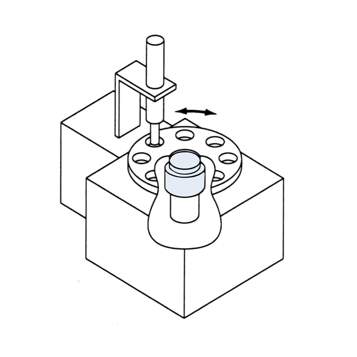
Zero-Backlash
Uses a steel ball in the deceleration mechanism instead of a gear. Eliminates backlash and enables prevision feeding and high-precision positioning through constant rolling contact via preload.
-
Compact & Simple
Has a reduction mechanism and input/output bearings built into its housing for compactness and ease of installation.
-
Maintenance-free
Its grease-filled reducer can be used without lubrication for its entire rated life. Also has no mounting position restrictions.
-
High Efficiency
Its transmission mechanism uses a large number of steel balls to achieve a high-efficiency drive. The rolling contact of the balls is similar to that of a ball screw, allowing extremely light operation and maximized capacity of any motor.
Model
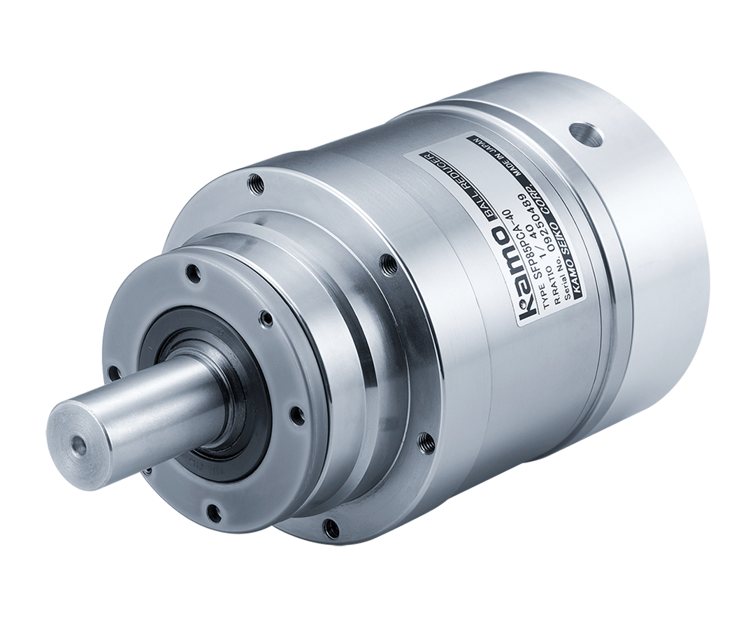
Ball Reducer (Input Shaft Type)
- BR
- 1
- 50
- 2
- S
- 3
- S
- G
- 5
- A
- 7
- X
- 8
- 1.Product Name
- BR series
- 2.Frame number
- 50,65,85,100,125,160
- 3.Output shaft shape
-
S:Shaft output
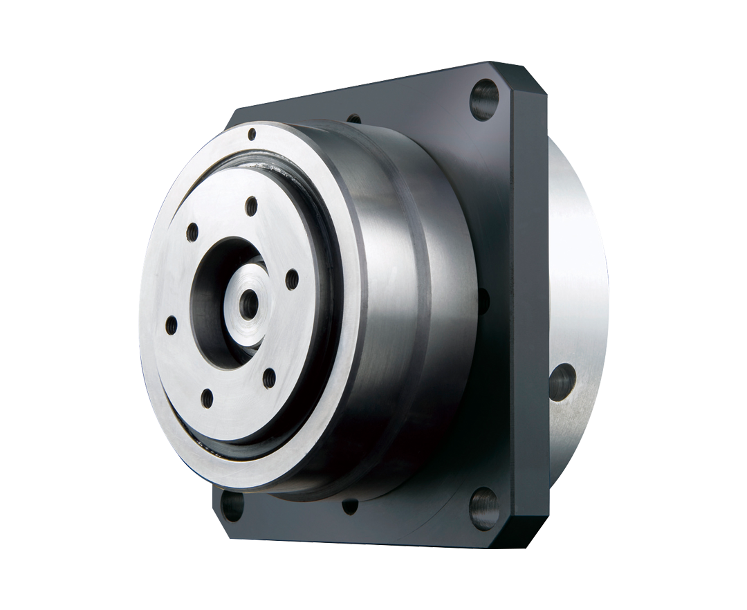
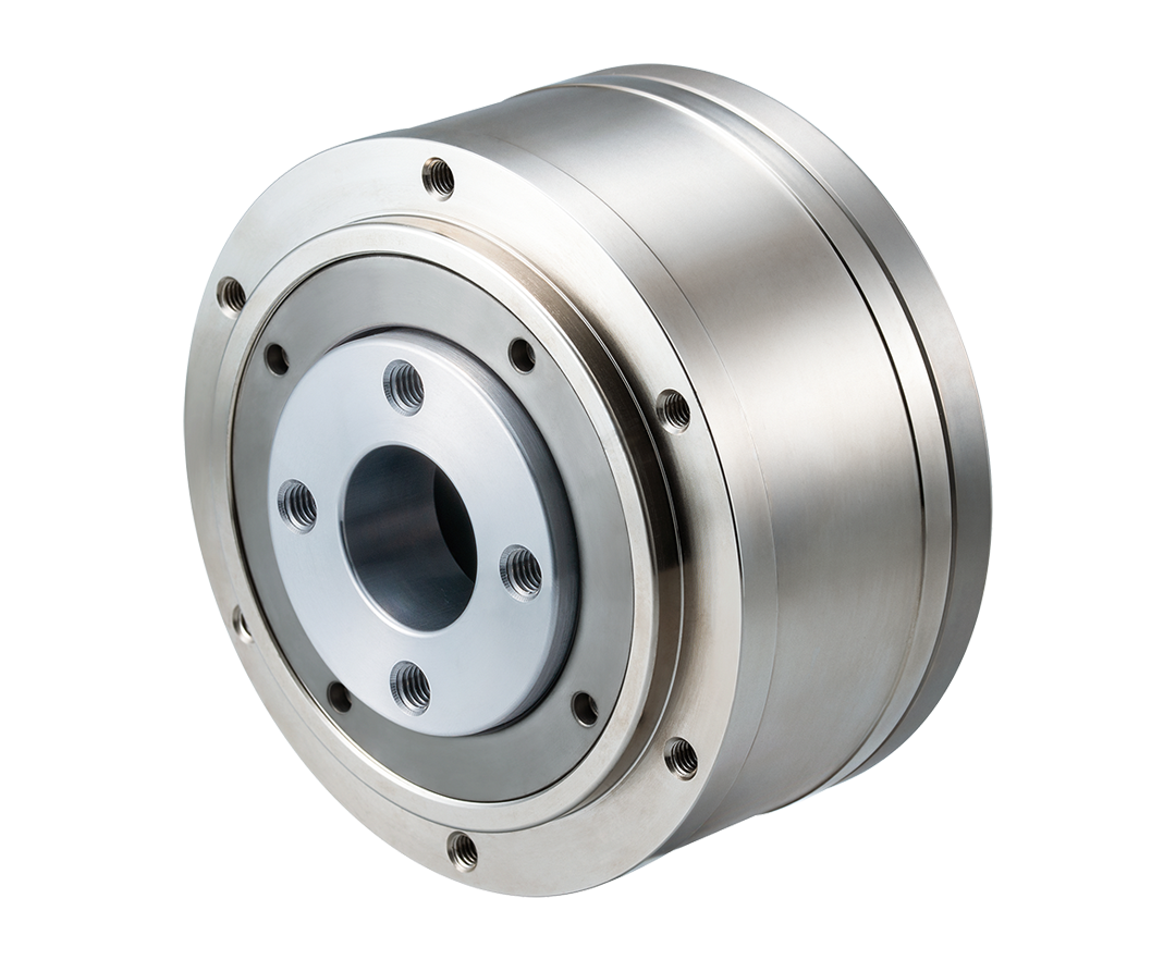
U:Flange output (KU for BR100 and 125 only)
- 4.Reduction ratio
-
Frame number 50:10,15,18
Frame number 65:10,15,20
Frame number 85:10,15,20,30
Frame number 100:10,20,30,40
Frame number 125:10,20,30,50
Frame number 160:10,20,30,50
- 5.Rotational Direction
-
G:Rev.
S:Fwd. (Rotational direction of the output shaft relative to the input shaft rotational direction)
- 6.Output shaft option code
-
No Code: No setting
Shaft Output Axis (S): 1:Keyless,2:Keyway, tip tap,3:”D”-cut,4:”D”-cut, tip tap
Flange Output (U): 5:Keyway, keyway tolerance P9,6:Keyway, keyway tolerance Js9
- 7.Input shaft option code
-
No Code: No setting
A:Keyless
B:Keyway, tip tap
C:”D”-cut
D:”D”-cut, tip tap
G:Short-length type for a coupling(A coupling sold separately)
- 8.Other option code
-
No Code: No setting
X:Drill-throu-hole housing
Ball Reducer (Input Shaft Type)
- BR
- 1
- 50
- 2
- U
- 3
- H
- G
- 5
- K
- 7
- 2
- 8
- E
- 10
- X
- 11
- 1. Product Name
- BR series
- 2.Frame number
- 50,65,85,100,125,160
- 3.Output shaft shape
-
S:Shaft output
U:Flange output (KU for BR100 and 125 only)
- 4.Reduction ratio
-
Frame number 50:10,15,18
Frame number 65:10,15,20
Frame number 85:10,15,20,30
Frame number 100:10,20,30,40
Frame number 125:10,20,30,50
Frame number 160:10,20,30,50
- 5.Rotational direction of output shaft
-
G:Rev.
S:Fwd. (Rotational direction of the output shaft relative to the input shaft rotational direction)
- 6.Input bore size
-
Please refer to the hole input type dimensions.(Catalog: P33)
- 7.Input Fastening Method
-
K:Key stopper
T:Tap stop
W:Key and tap stopper
- 8.Key Width Dimensions
-
Please refer to the key groove dimension table.(Catalog: P33)
- 9.Output shaft option code
-
No Code: No setting
Shaft Output Axis (S):1:Keyless,2:Keyway, tip tap,3:”D”-cut,4:”D”-cut, tip tap
Flange Output (U): 5:Keyway, keyway tolerance P9,6:Keyway, keyway tolerance Js9
- 10.Input shaft option code
- No Code: No setting, E:Keyway, keyway tolerance Js9
- 11.Other option code
- No Code: No setting, X:Drill-throu-hole housing
Specifications
| Model |
|---|
| Reduction ratio |
Rotational Direction |
Allowable rated torque (N・m) |
Acceleration peak torque (N・m) |
Max. Instantaneous torque (N・m) |
Allowable average number of input revolutions (rpm) |
Max.Input rpm (rpm) | Moment of inertia at Input shaft (x10-4 kg・m2) |
At end of output shaft | At end of input shaft | Mass weight (kg) | Outline Drawing | CAD Data | Catalog | Instruction Manual |
||||
|---|---|---|---|---|---|---|---|---|---|---|---|---|---|---|---|---|---|---|
| Allowable radial load (N) | Allowable thrust load (N) | Allowable radial load (N) | Allowable thrust load (N) | U type | S type | U type | S type | |||||||||||
| BR50 |
|---|
| BR65 |
| BR85 |
| BR100 |
| BR125 |
| BR160 |
| 10 | Reverse | 3.9 | 9.8 | 19.6 | 2400 | 3000 | 0.021 | 29 | 79 | 49 | 29 | 0.36 | 0.4 | CAD | ||||
| 15 | Forward | 3.9 | 9.8 | 19.6 | 0.018 | |||||||||||||
| 18 | 3.9 | 9.8 | 19.6 | 0.017 | ||||||||||||||
| 10 | Reverse | 7.8 | 14.7 | 29.4 | 2400 | 3000 | 0.053 | 98 | 294 | 49 | 49 | 0.7 | 0.9 | |||||
| 15 | 7.8 | 14.7 | 29.4 | 0.048 | ||||||||||||||
| 20 | 6.9 | 12.7 | 25.5 | 0.043 | ||||||||||||||
| 10 | Reverse | 19.6 | 37.3 | 73.5 | 2400 | 3000 | 0.19 | 294 | 588 | 108 | 74 | 1.45 | 1.8 | |||||
| 15 | 17.7 | 33.3 | 65.7 | 0.16 | ||||||||||||||
| 20 | 15.7 | 29.4 | 58.8 | 0.15 | ||||||||||||||
| 30 | Forward | 14.7 | 27.5 | 54.9 | 0.14 | |||||||||||||
| 10 | Reverse | 34.3 | 58.8 | 117.7 | 2300 | 3000 | 0.65 | 490 | 981 | 147 | 98 | 3.0 | 3.6 | |||||
| 20 | 31.4 | 53 | 105.9 | 0.52 | ||||||||||||||
| 30 | 24.5 | 42.2 | 82.4 | 0.5 | ||||||||||||||
| 40 | 24.5 | 41.2 | 83.4 | 0.44 | ||||||||||||||
| 10 | Reverse | 68.6 | 117.7 | 235.4 | 2200 | 3000 | 1.81 | 785 | 1471 | 186 | 147 | 4.9 | 6.4 | |||||
| 20 | 68.6 | 117.7 | 235.4 | 1.4 | ||||||||||||||
| 30 | 51 | 86.3 | 172.6 | 1.28 | ||||||||||||||
| 50 | 44.1 | 74.5 | 150 | 1.17 | ||||||||||||||
| 10 | Reverse | 98.1 | 176.5 | 353 | 2000 | 2500 | 5.2 | 981 | 1961 | 441 | 294 | 10.5 | 14.2 | |||||
| 20 | 98.1 | 176.5 | 353 | 4.07 | ||||||||||||||
| 30 | 94.1 | 168.7 | 338.3 | 3.61 | ||||||||||||||
| 50 | 62.8 | 112.8 | 225.6 | 3.33 |