Technical Information – Precision Reducers
Problems with Gear-type Reducers
What is a Reducer?
A reducer is a device that decelerates and outputs torque proportional to the deceleration. It achieves this by combining gears having different numbers of teeth with the rotational speed and power (torque) obtained from a power source such as a motor.
Reducers adjust the speed and generate larger torques than motor torques by reducing the rotational speed, obtaining the required rotational speed and torque from motors rotating at constant speeds.
The reduction mechanism is relatively easy to achieve through a combination of flat gears with varying numbers of teeth. Commonly used reducer types include device gear (helical, bevel, hypoid) reducers, planetary reducers, cyclo reducers, wave reducers, and Ball Reducers.
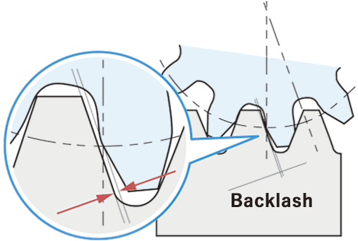
Presence of Backlash
Backlash (gaps) is essential if the reducer is based on an involute gear mechanism.
To achieve Zero-Backlash, there must be no gaps between the components of the reducer, with constant contact being a prerequisite.
Disadvantages and Issues Caused by Backlash
- Deterioration in stopping accuracy
- Noise and vibration due to teeth rattling
- Wear and dust generation in the meshing area
Reducers are required a wide range of features to meet the demand for higher precision/performance in machinery and equipment
Reducers in recent years have been required the features below to achieve higher precision/performance in machinery and equipment.
These have become indispensable for modern servo motor controllers, which require precision feeding and positioning.
- Zero-Backlash
- Small, Compact, Space-saving
- High Angle Transmission Accuracy
- High Efficiency
- Low noise
- Low Vibration
- Low Inertia
- High rigidity
Ball Reducer – BR series, JFR series, SFP series
What is a Ball Reducer?
A Ball Reducer is a reducer with a Zero-Backlash mechanism that solves the problems of gear reducers.
- This is achieved through the following mechanisms:
- Instead of gears, steel balls are interposed as rolling elements to transmit power through constant rolling contact.
The backlash is reduced to zero by applying preload to the power transmission part (meshing part).
The steel ball transmission eliminates backlash and allows for light power transmission without increased friction.
This basic idea has been effective in ball bearings, ball screws, and even linear guides.
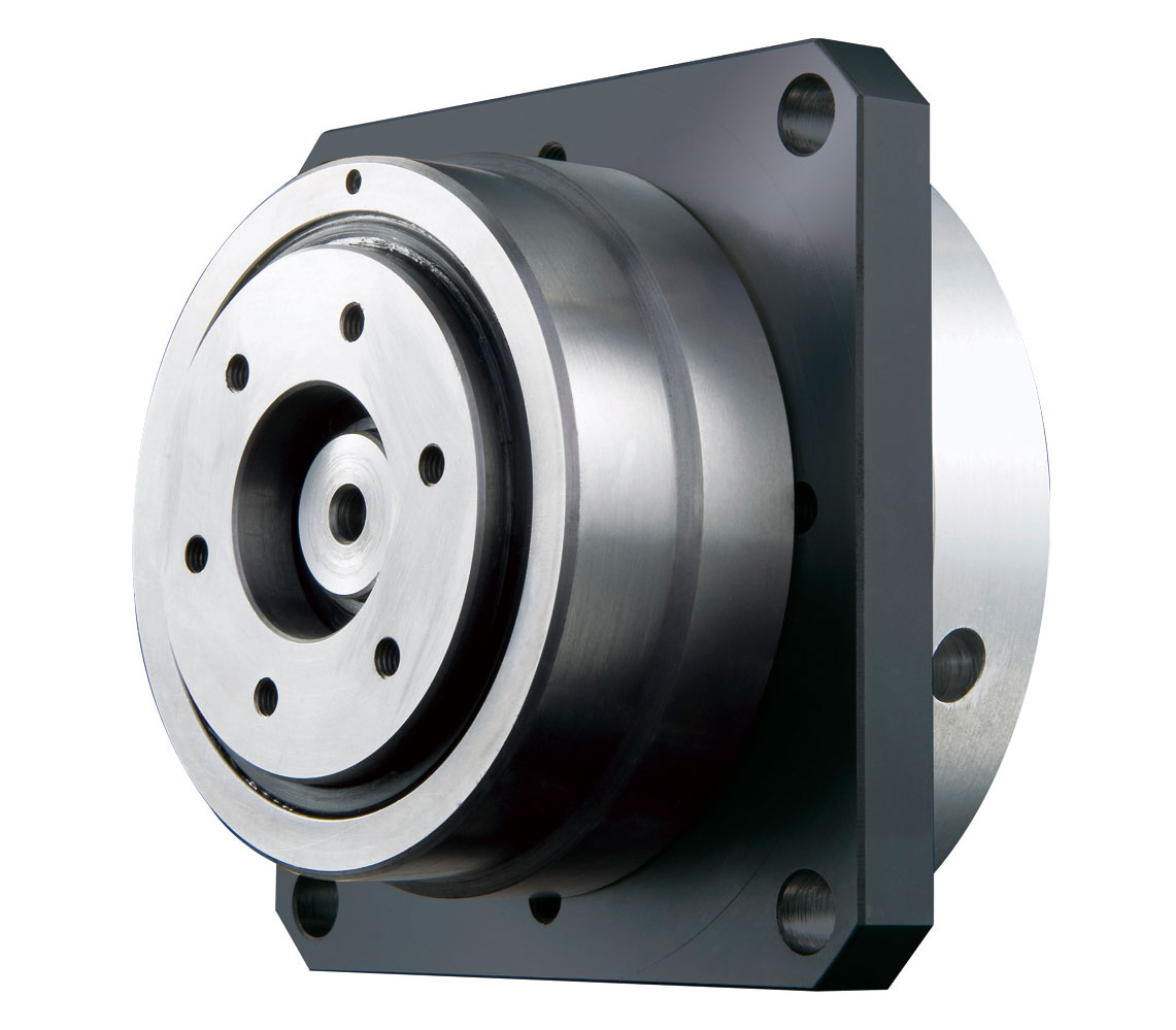
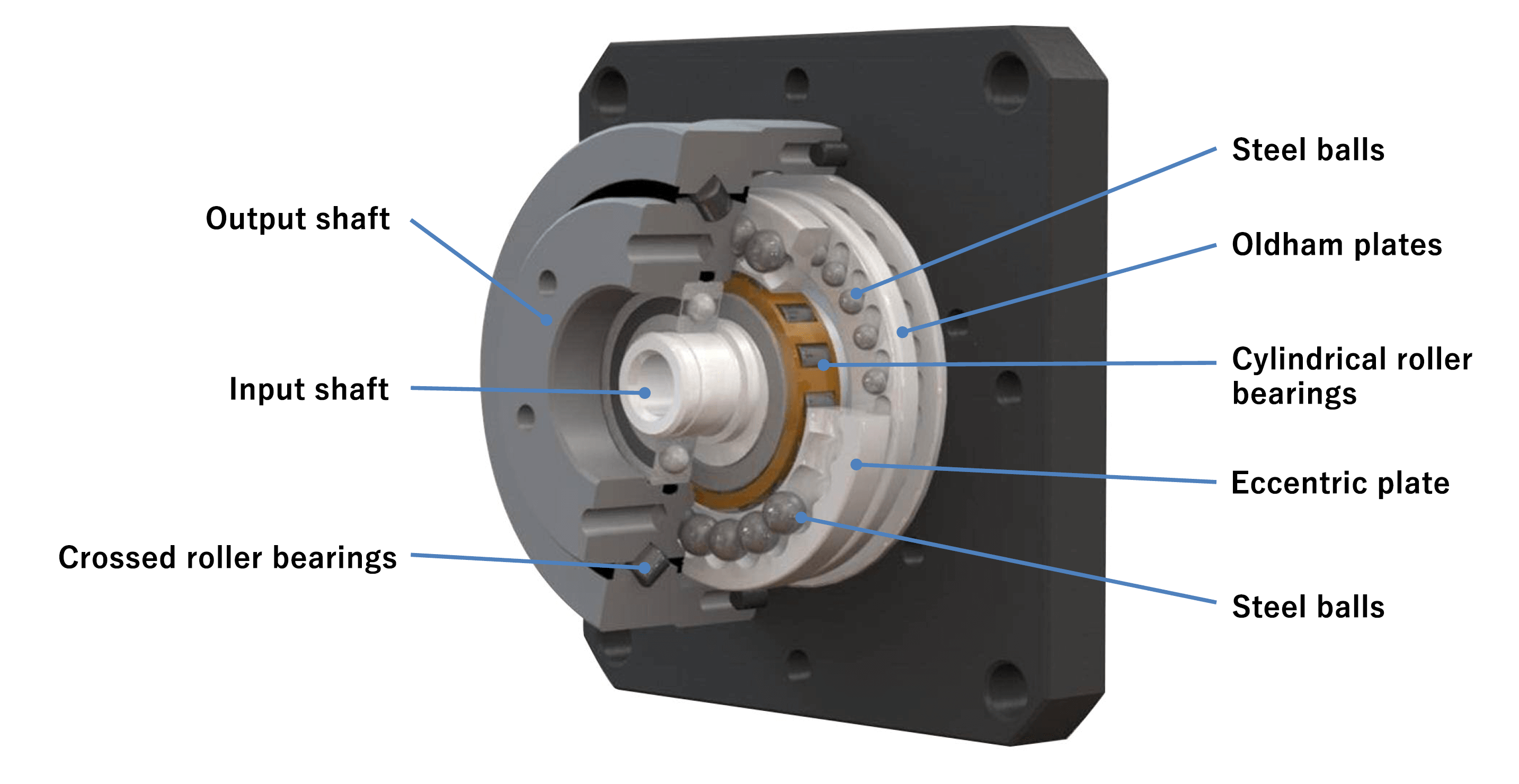
Ball Reducer Structure
The structure of the Ball Reducer is similar to a kind of differential gear mechanism with internal and external gears. However, it transmits power via steel balls rather than gears, leading to less friction and smoother operation.
Almost all the balls are involved in the transmission of motion, boosting transmission efficiency. It also achieves Zero-Backlash by applying preload to the meshing area to eliminate gaps.
Operating Principles of the Ball Reducer
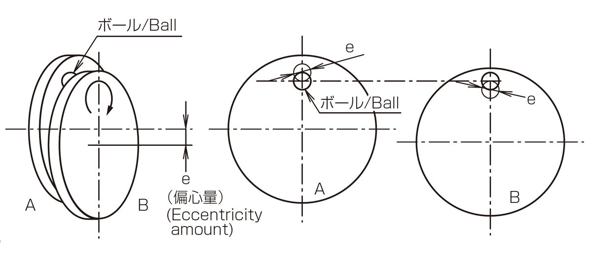
The Ball Reducer is a reduction mechanism that applies a cycloid curve.
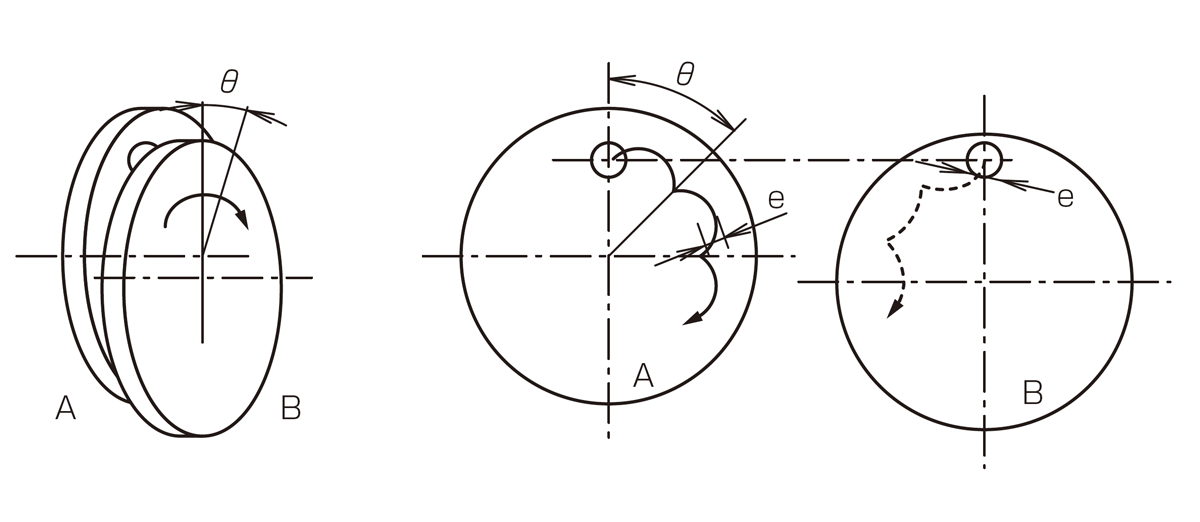
As shown in Fig. 1, when a ball is placed between two discs, one of which is fixed and the other is subjected to an orbital rotation with an eccentricity of e, the balls roll on each disc in a circular path of diameter e.
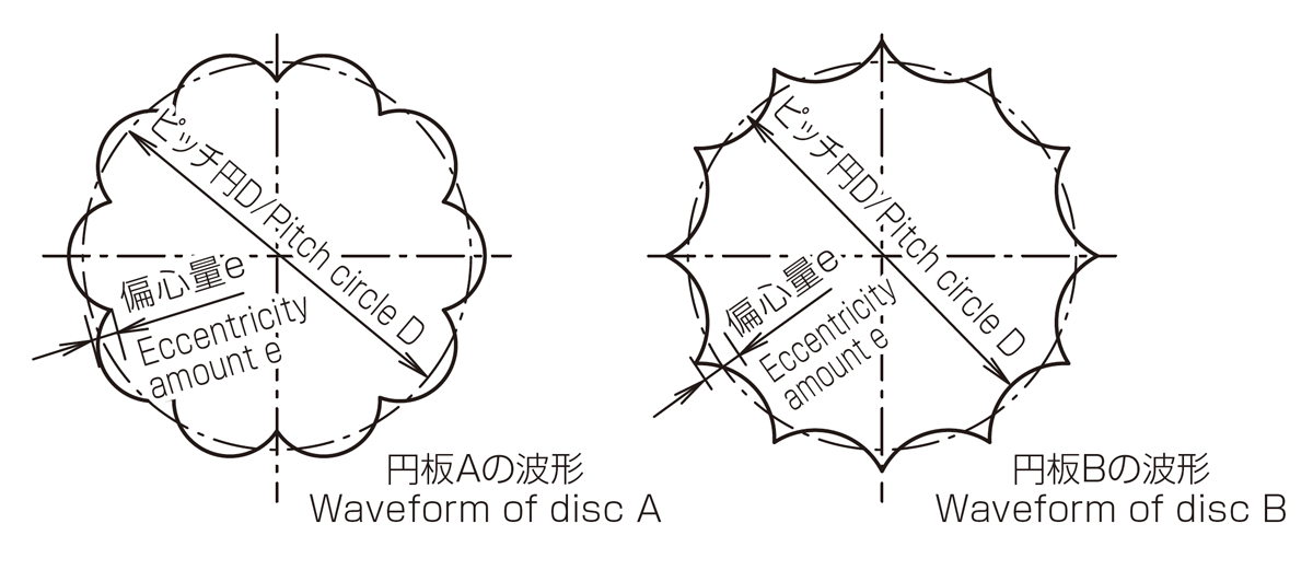
Furthermore, as shown in Fig. 2, for one revolution of the orbiting disk, if the orbital revolution is given while the rotation of θ degrees is given, the trajectory of the ball will draw an epicycloid curve with amplitude e for the stationary disk, and a hypocycloid curve with the same amplitude for the orbiting disk (or a trochoid curve).
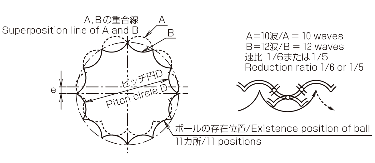
Reversing this idea, we have Fig. 3. In other words, a disc with an epicycloid curve on one side, and a disc having a ball groove with a hypocycloid curve as the central locus on the other side, are placed facing each other with a ball as the rolling element. When one disc is fixed, and the other is subject to an orbital rotation, the orbiting disc experiences a rotation proportional to the difference in the wavenumbers between the two discs.
This mechanism eliminates this rotation using the two moving plates having circular grooves in Fig. 1. It is completely equivalent to the rotation and revolution generated by the rolling motion of the large and small discs.
As shown in Fig. 4, there are several points of contact between each curve, where the balls are located. As such, all the balls are necessarily constrained (meshing) by the grooves, with the rolling contact used for rolling and torque transmission.
Character and Merit of Ball Reducer
Zero-Backlash
Ball reducers do not have the backlash at the power transmission section, therefore it is possible that high accuracy positioning and feeding.
Compact and Simple design
By integrating a reducer mechanism and an input / output part into the housing the uit is assembled to be compact size, and the reducer with the concentricity of the input / output has materialized no dead space installation.
Maintenance-free
Lubricating grease for Reducer is already filling, so it makes possible to be free of maintenance procedures.
Mounted to any motors
With simple flange arranged, it is possible to cope with any types of motors.
Low noise
There is only rolling ball noise due to the rolling contact of steel balls at all power transmission sections. There is no meshing or flexing gear noise at all.
High Efficiency
Almost all balls are involved in power transmission, therefore transmission efficiency is high, and the rolling contact of the balls makes it extremely smooth motion like ball screws.
Thin Differential Reducer – PSR series, PSL series
What is a Thin Differential Reducer?
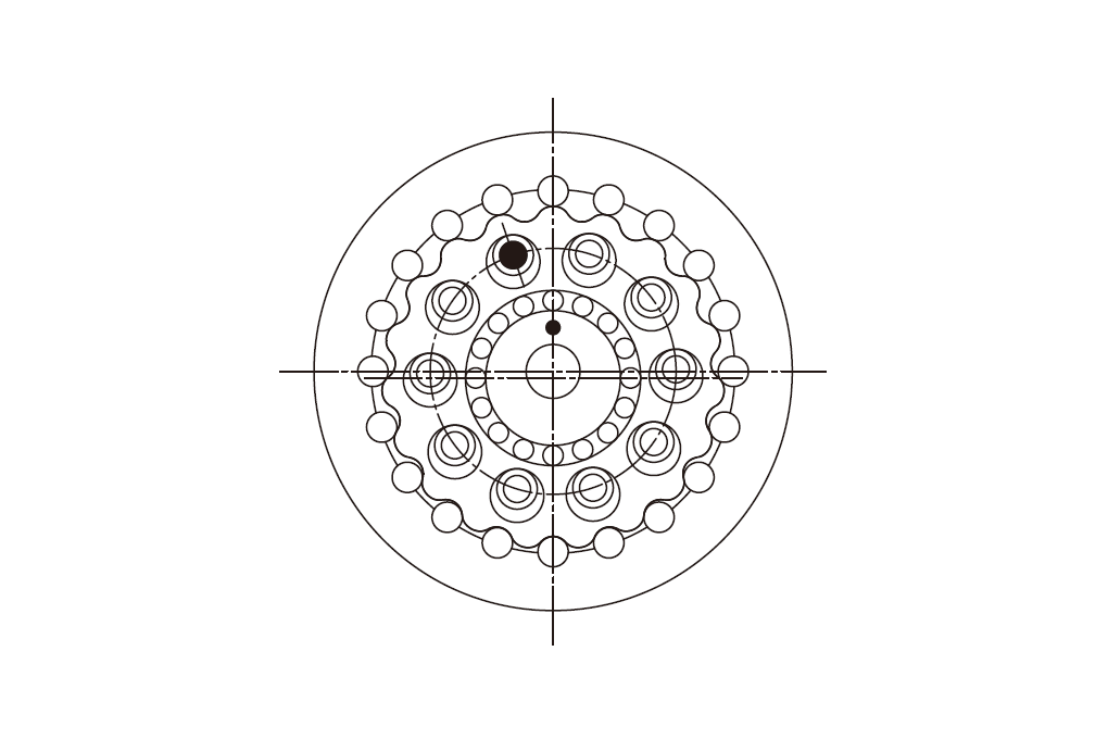
The Ultra-Thin Differential Reducer outputs power via a clever pin-and-hole system and cross roller bearing support, with two highly reliable trochoidal gears arranged inside circumferentially arranged rollers as robust and precise ultra-thin counterparts.
Structure of the Thin Differential Reducer
The Thin Differential Reducer enables ultra-flat profiles via a differential reduction mechanism and thin cross roller bearings.
Its structure consists of trochoidal gears, rollers, and carrier pins and has a high meshing ratio with extremely high rigidity. It can also take the entire load and has a higher transmission accuracy through multiple meshing of power transmission parts.
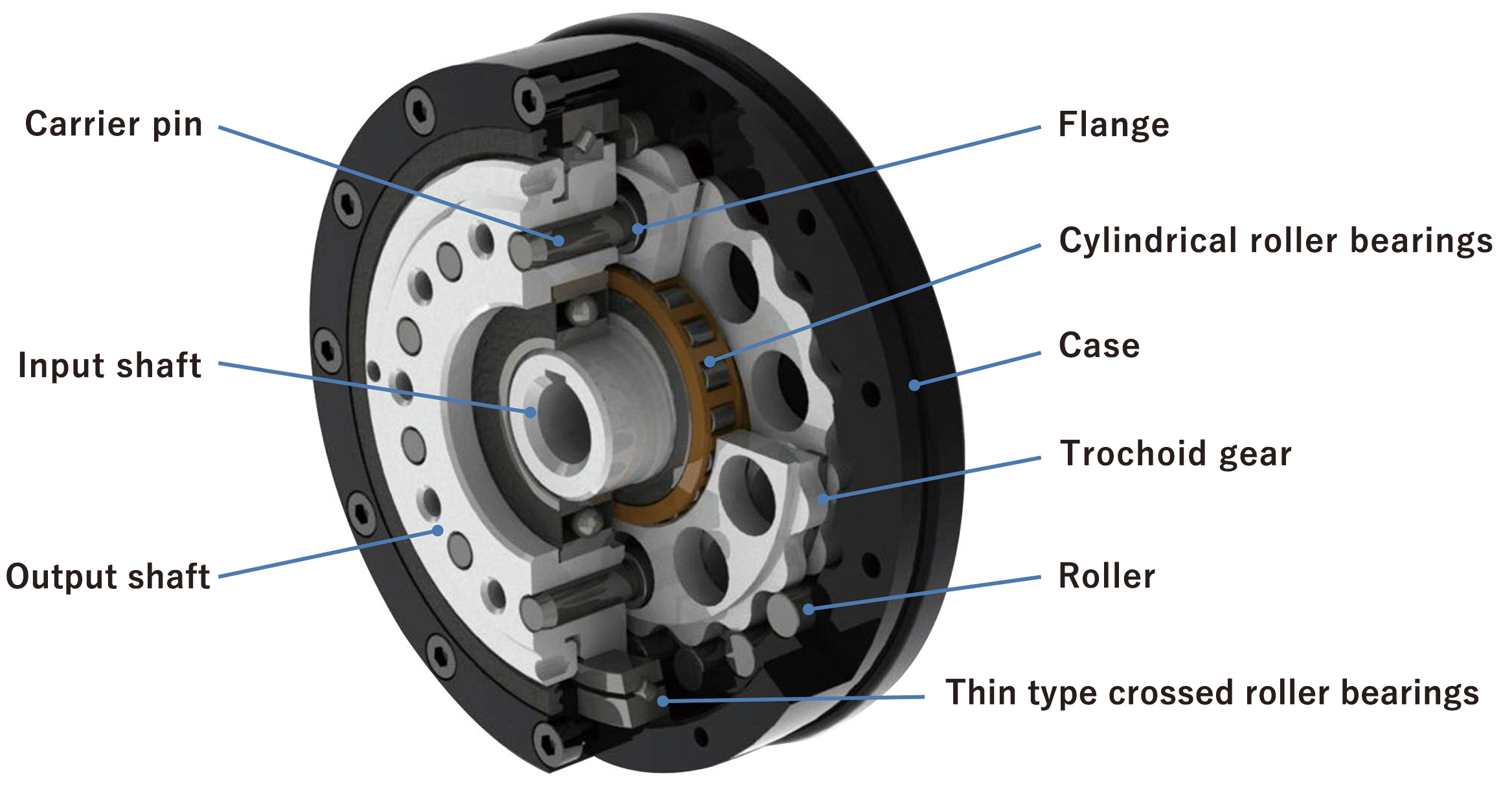
In the lightweight model PSL, six out of eleven major machined parts are aluminum, achieving approximately 30% weight reduction.
Operating Principles of the Thin Differential Reducer
Differential Reduction Mechanism Section
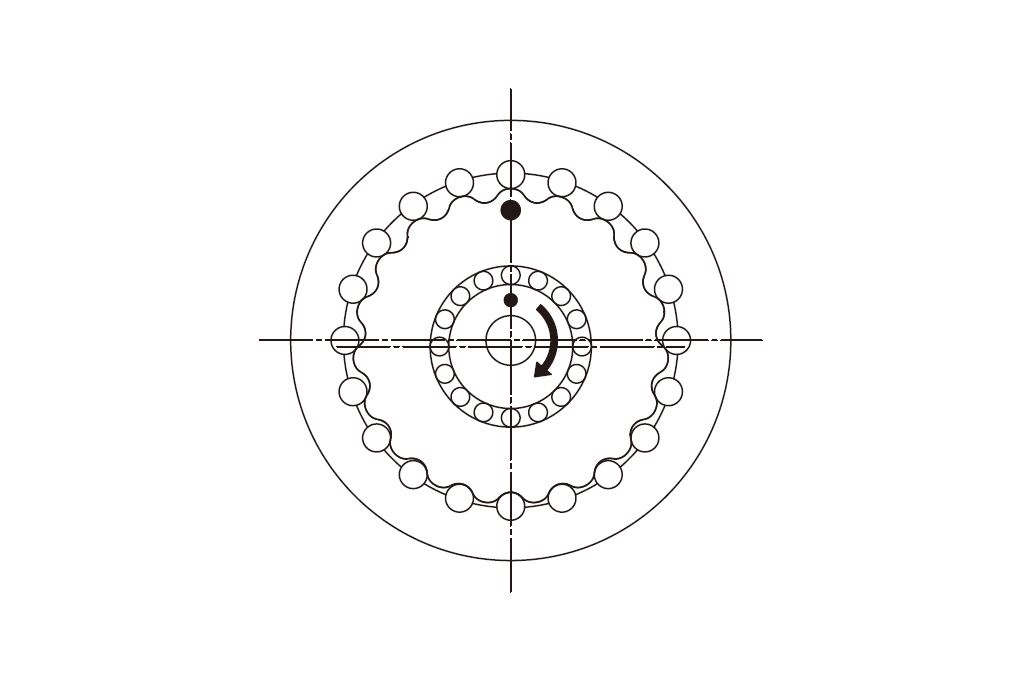
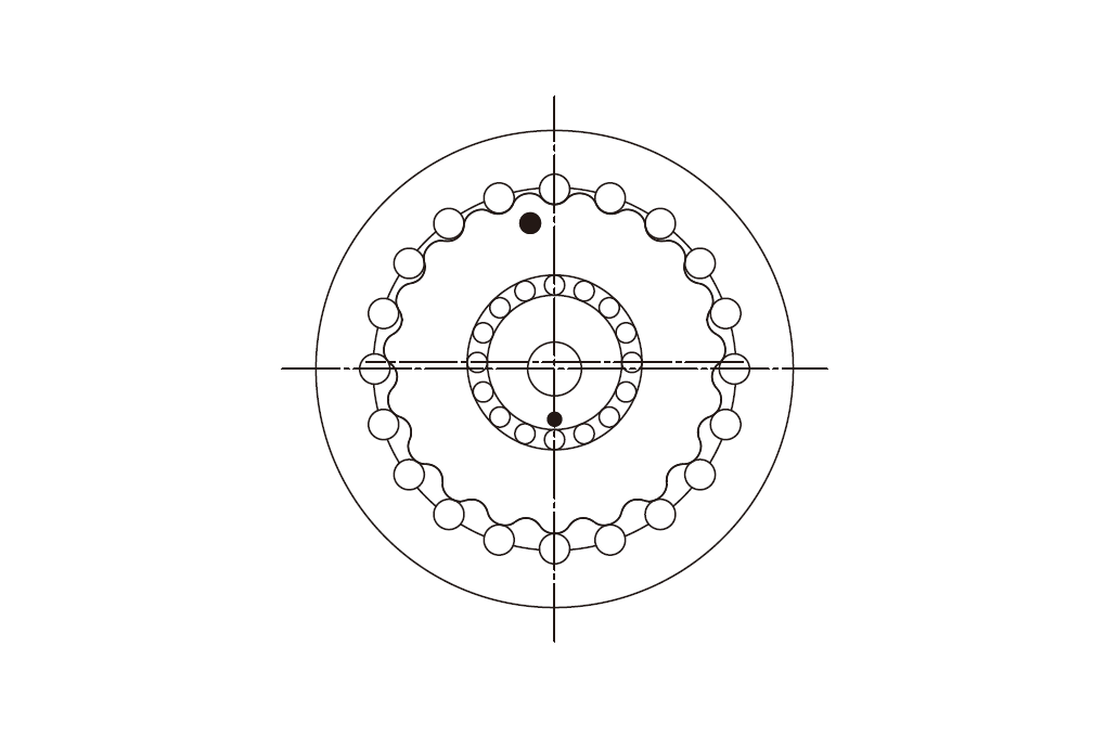
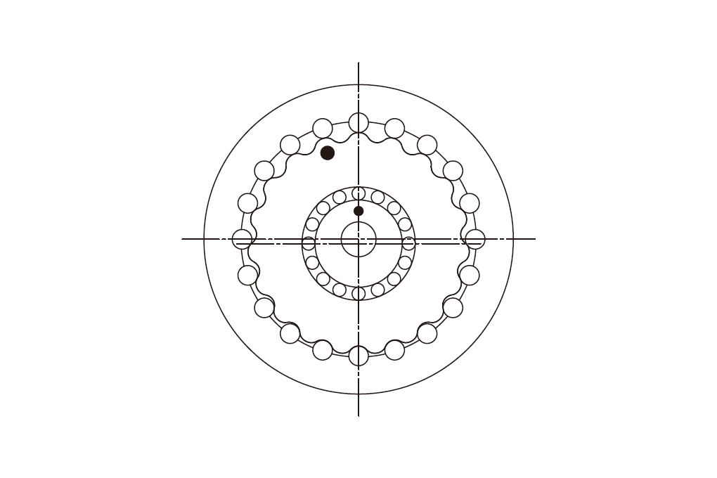
The differential reduction mechanism consists of an internal gear composed of rotating rollers fitted into the case, and a trochoidal gear supported on the eccentric of the input shaft via bearings.
When the input shaft is rotated once, the trochoidal gear rotates in the opposite direction by one tooth. The ratio of the amount of rotation between the input shaft and the trochoidal gear is the speed ratio.
Eccentric Constant Velocity Mechanism
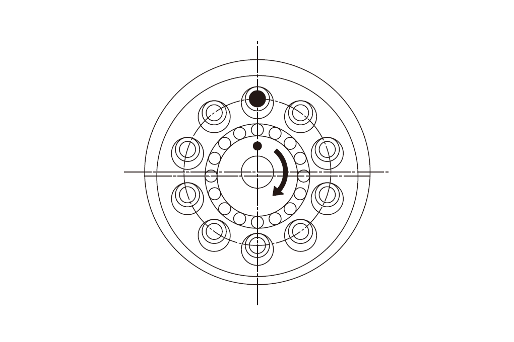
Out of the orbital rotation and trochoid gear rotation generated by the differential reduction mechanism, the eccentric constant velocity mechanism transmits only the trochoid gear rotation to the output shaft.
A bushing is fitted to several carrier pins fixed to the output shaft. The small hole in the trochoid gear then rotates in orbit while making contact with the bushing, transmitting only the rotation to the output shaft at a constant speed.
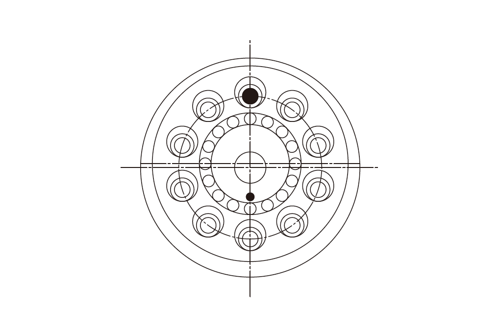
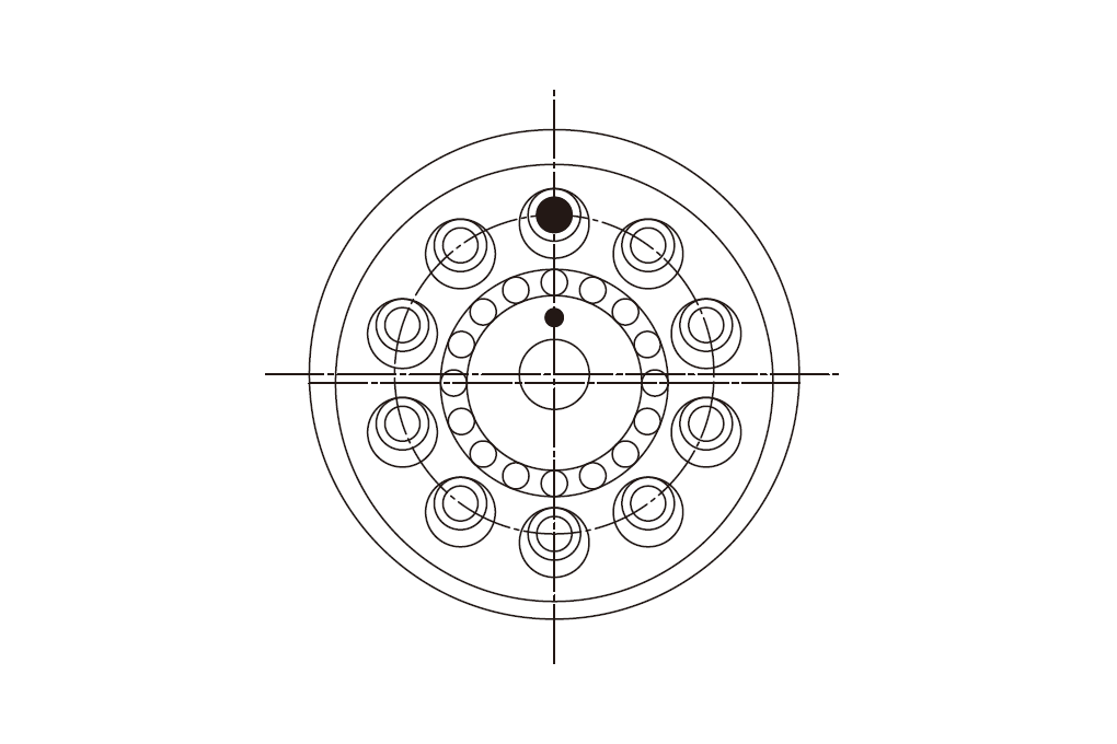
Internal Mechanism
The differential reduction mechanism and eccentric constant speed mechanism accurately and smoothly reduce the input shaft rotation, transmitting it to the output shaft.
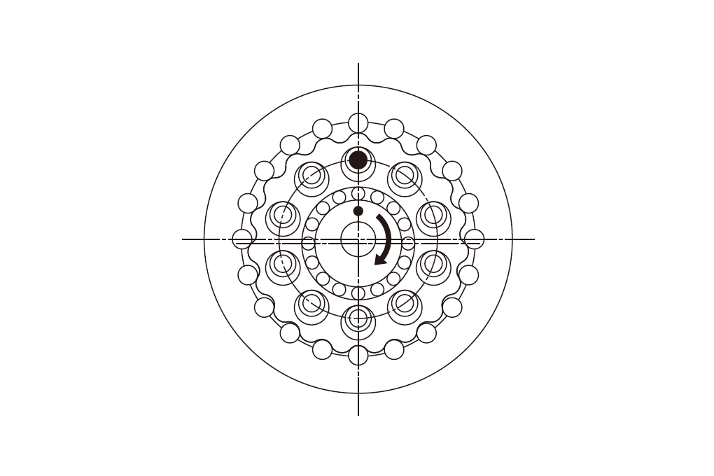
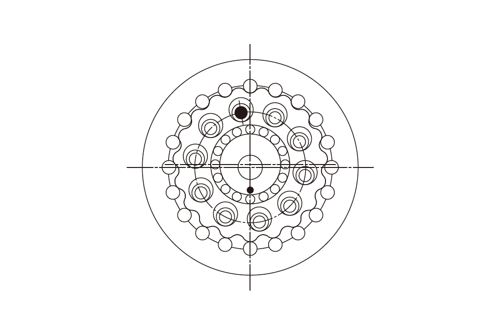
Character and Merit of Thin Differential Reducer
Ultra-flat and compact design
The adoption of a differential reduction mechanism and a thin cross-roller bearing has enabled an ultra-flat form.
This contributes to the realization of contraction and compactification of equipment.
High rigidity
High contact ratio and load dispersion have realized extremely high rigidity.
High Accuracy
Plural meshing of precision trochoid gears and high-precision rollers has realized high-precision transmission.
High Efficiency
Appropriate pressure angle setting has made operation smooth and highly efficient.
High efficiency – Backdrivability
Features excellent back-drivability (reverse rotation efficiency) when rotated from the output shaft side due to high reduction efficiency.
Recent focused industrial equipment such as cooperative robots and AGVs tend to be battery-powered and characterized by human collaboration. Good back-drivability is very useful here because it allows them to be restored to their original state via human power during emergencies (such as battery failures or emergency stoppages).
Small backlash
The optimization of each part clearance enables high-precision positioning with the backlash.
Light Weight – PSL sereis
Released the light weight model “PSL” which is used Aluminium to the main construct part for Reducer.
By changing the material of 6 out of 11 component parts, this is realized to decrease the mass about 30% from the conventional model.
