Technical Information – Index Actuator
What is an Index Actuator?
There are indexing devices that perform intermittent, periodic stop-position-stop actions in one direction. Some indexing devices also operate by switching from linear motion to rotational.
There are three types of cam-type intermittent indexing equipment: roller gear cam, parallel cam, and barrel cam.
There are sections where the output axis is indexed in one input rotation (index angle) and others where the output axis is stationary (stationary angle). In stationary sections, the output shaft does not rotate when the input shaft is rotating, allowing positioning even with an induction motor or the like. (For four-division indexing devices, when the input shaft makes one rotation, the output shaft rotates 90 degrees.)
On the other hand, cam-type indexing devices set the number of divisions per movement by determining the amount of movement of the output shaft based on the curvature (shape) of the cam meshing with the piston’s linear movement.
Indexing machines are widely used as base machines for multi-process rotary-type automatic assembly machines, automatic packaging machines, and the like due to their ability to perform multi-division indexing (such as four or twelve-division indexing).
Pearldex – PDW series
What is Pearldex?
Pearldex is a barrel cam mechanism with a very simple structure consisting of three basic parts: the cam, wheel, and follower.
By replacing the driven element with a steel ball, the index size is reduced compared to conventional barrel cam indexes.
Rotating the cam at a constant speed makes the output shaft follow the cam curve, resulting in intermittent rotational movements.
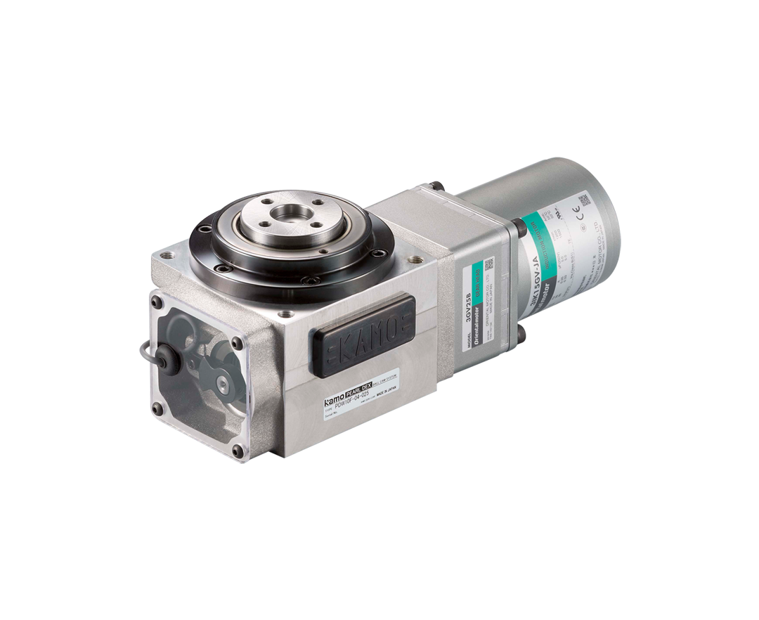
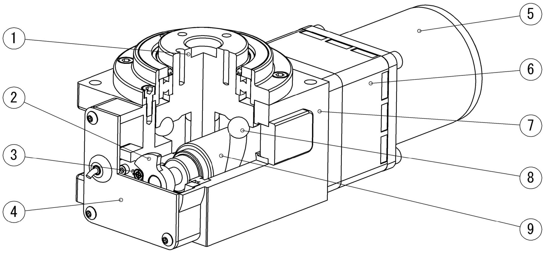
Structure of Pearldex
The PDW Series consists of a motor with gear head, a proximity sensor, and a dog unit.
- 1
- Output shaft
- 2
- Dog
- 3
- Proximity sensor
- 4
- Sensor cap
- 5
- Induction motor
- 6
- Gear head
- 7
- Casing
- 8
- Steel balls
- 9
- Cam shaft
Principles of Pearldex
Pearldex’s cam curve uses a modified sine curve (MS curve) to achieve smooth motion characteristics.
A1 and A2 in the figure are straight lines that do not change in the axial direction as the cylinder rotates. B is the part that moves with changing speed in the axial direction as the cylinder rotates at a constant speed, which becomes a deformed sine curve.
C1 and C2 are the same transformed sine curve as B. They are the entry and exit of the driven body and are interrupted.
A1 and A2 are the stopping angles, and B is the indexing angle. The indexing operation is completed when the driven body moves from A1 to A2.
About Index count, Assignment angle and stationary angle
In Pearldex, the output shaft repeats intermittent rotation by rotating the camshaft. The number of times it stops during one output shaft rotation is called the division.
The angle of rotation of the camshaft required to index the output shaft is called the assignment angle. The angle at which the output shaft is stationary is called the stationary angle.
Within the stationary angle’s range, the output shaft stops and holds even if the camshaft is rotated.
Character and Merit of Pearldex
Unitization
Gear head, Induction motor, Sensor, and Dog as a unit.
Cam Curves
Uses the modified sign acceleration curve (MS curve) to achieve smooth motion characteristics.
Maintenance-free
Lubricating grease for PDW is already filling, so it makes possible to be free of maintenance procedures.
Small
Features a compact shape from 60 to 160 square meters.
Low Cost
Low cost achieved by unitization.
Air Index Cylinder – MDF series
What is the MDF Series?
The MDF Series features air cylinder type indexers that complete one-division indexing operations with a one-way piston movement using cams on both ends of the piston.
It is made up of simple elements, boasting durability and compactness.
Structure of the Air Index Cylinder
- 1
- Bearing nut
- 2
- Deep groove ball bearing
- 3
- One-way clutch
- 4
- Follower cap
- 5
- O-ring
- 6
- Tube
- 7
- Cam piston
- 8
- Shaft
- 9
- Cam cap
- 10
- Circlip
- 11
- Air port
- 12
- Air port
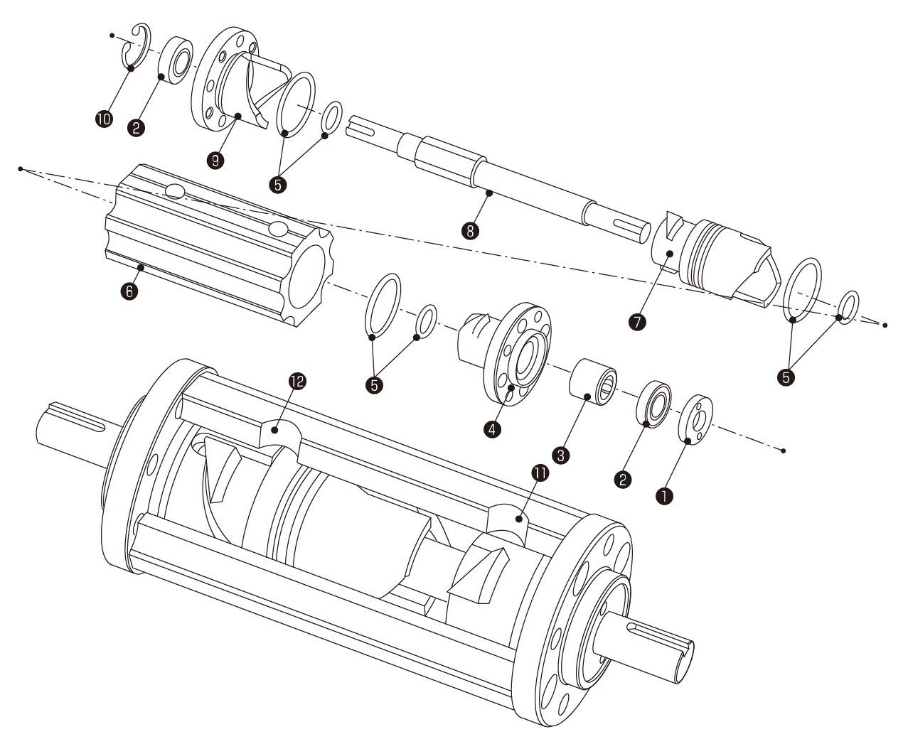
*This figure shows MDF30.
*All sealing parts are JIS standard products.
*Reverse rotation is not possible due to the internal one-way clutch operation.
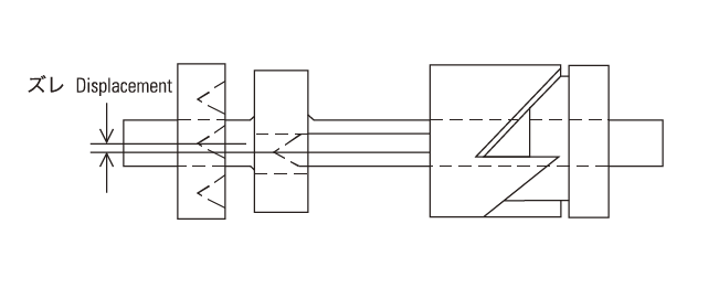
Operating Principles of Air Index Cylinders
Every time the internal piston moves one way, it completes indexing one division.
Indexing Completed (Stopped)
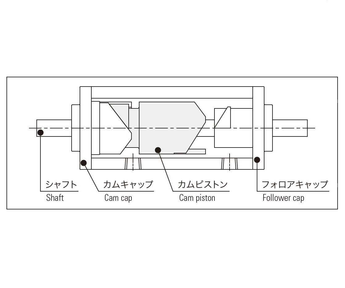
The cam piston and cam cap mesh together.
Indexing
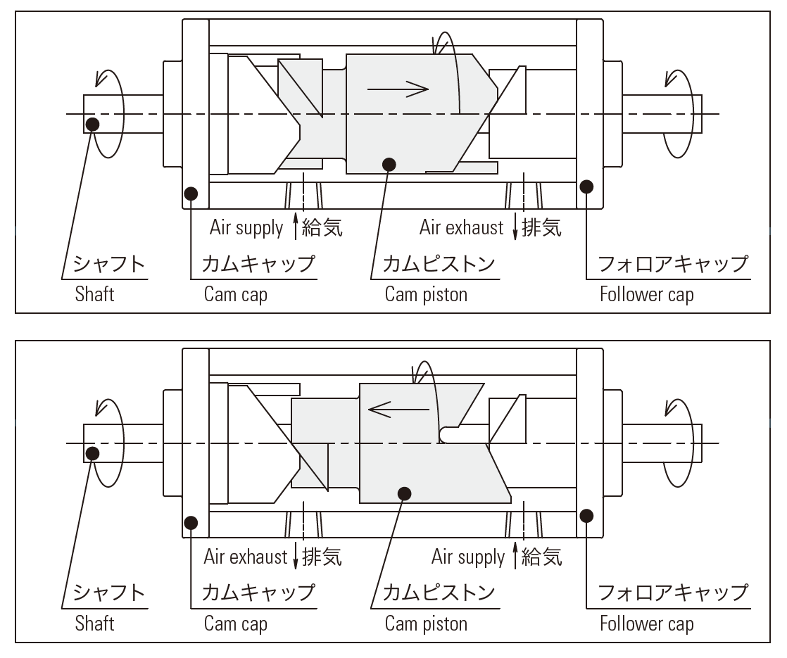
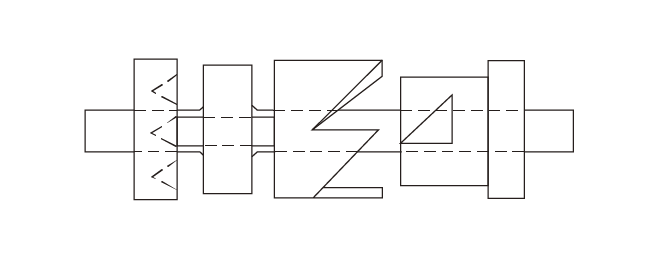
The cam piston moves linearly in the right (left) direction via valve switching. When it disengages with the cam cap (follower cap), it begins meshing with the follower cap (cam cap). The cam piston then rotates, and its rotation is transmitted to the shaft.
Indexing Completed (Stopped)
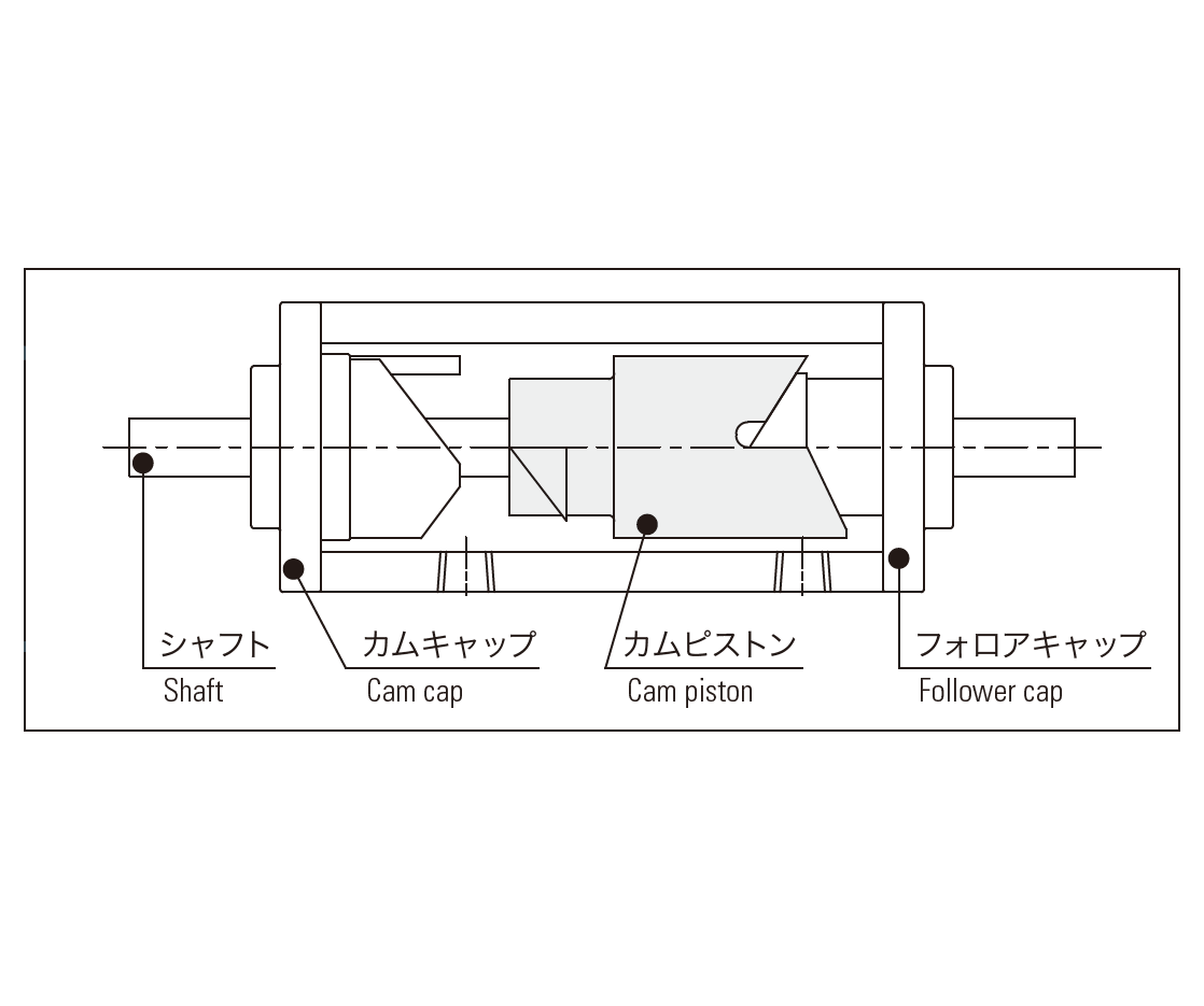
The cam piston and follower cap are now fully engaged, completing one division.
Character and Merit of Air Index Cylinder
Simple Control
Easy indexing via air control like an air cylinder. *Double solenoid valve is recommended.
The unidirectional rotation by cams and the double-shaft type enable any direction of rotation.
High Accuracy
Indexing via cams does not cause cumulative errors
No shaft return due to the built-in one-way clutch and no overrun due to the reliable indexing stop structure.
Maintenance-free
Lubricating grease for MDF is already filling, so it makes possible to be free of maintenance procedures.
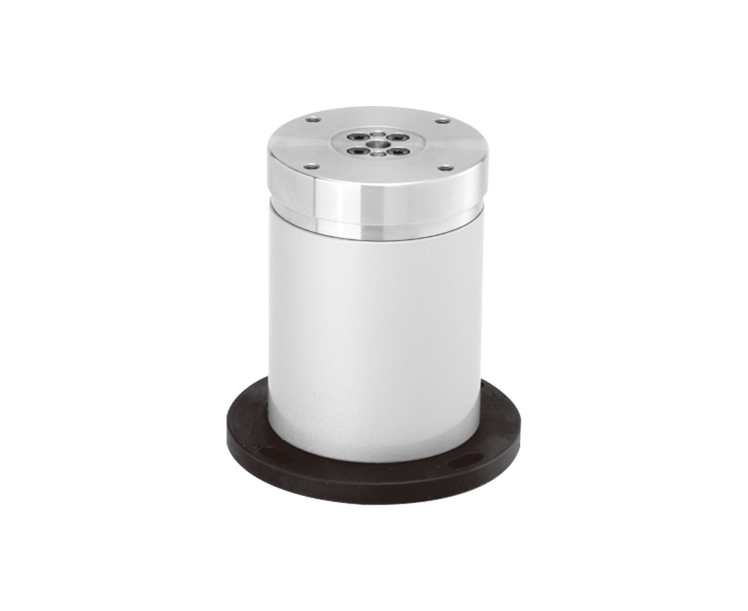
Air Index Table – MT series
What is the MT Series?
The MT Series features index table units with improved indexing accuracy and rigidity, based on the indexing principles of the air index cylinder.
This series performs indexing operations only by air piping from a 4-way valve, allowing it to be easily mounted on small drilling machines or tapping machines to save labor.
It can also be incorporated into assembly machines by effectively utilizing its compact size, boasting a very wide range of applications.
Structure of Air Index Tables
- 1
- Rotating table
- 2
- Tube
- 3
- Follower cap
- 4
- Hole cap
- 5
- Piston
- 6
- Indexing plate
- 7
- Bell cam
- 8
- Locate pin
- 9
- Thrust bearing
- 10
- Ball bearing
- 11
- One-way clutch
- 12
- Shaft
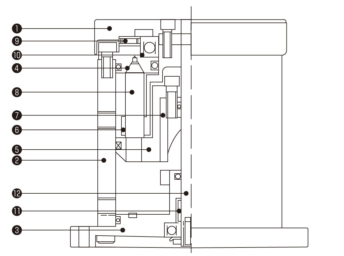
*MT70 model does not include (9) thrust bearing and (11) one-way clutch.
*All sealed parts are JIS standard products.
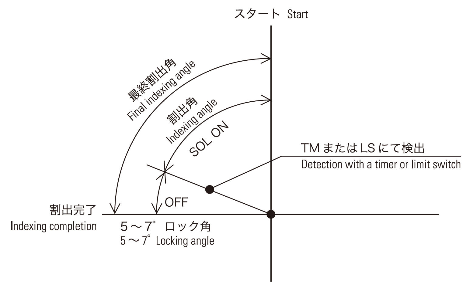
Operating Principles of Air Index Tables
Operation Outline
The indexing operations are performed by two-stage motions.
As shown in the figure below on the right, locking requires about 5° of movement. Please take this into consideration when using this product.
Also, note that the torque during locking is always greater than the torque during indexing.
1. Stopped (In-place)
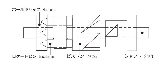
Indicates the status of the positioning lock. The piston is pushed to the left. The locating pin is fitted with the hole cap, securely locking the shaft.
2. Index
When the valve is switched, the piston moves to the right, and the indexing is completed. In this state, 95% of indexing is completed, and the piston is locked. At this time, the center of the locating pin is slightly offset from the center of the positioning hole.
3. Lock
The device returns to its original position. When the locating pin enters the hole, it enters with the approximately 5° leftover indexing operation and is locked again.
Character and Merit of Air Index Table
Simple Control
Easy indexing via air control like an air cylinder. *Double solenoid valve is recommended.
High Accuracy
Indexing via cams does not cause cumulative errors
Two-step indexing mechanism via cams and locating pins ensures reliable indexing and stopping operations for high-precision positioning.
High rigidity
Can reliably take the entire load due to the thrust bearing being built into the table section.
Maintenance-free
Lubricating grease for MT is already filling, so it makes possible to be free of maintenance procedures.